Desk Backlighting - Part 1
written on 10 May 2018
For a long time I have wanted to add some sort of back-lighting to my desk. I finally devised a realistic plan, which I will write about in this post.
You can tell by my previous posts that I enjoy toying with LED strips. I’m really fond of LED because they’re fairly cheap now days, and they are also fairly easy to interact with. You can use and Arduino, a Raspberry Pi, or even a remote control if micro-controllers aren’t your cup of tea.
I have also been experimenting with the Prusa i3 MK3 3D printer at school, so I felt this project gave me a real excuse to utilize it.
I actually did this back in march, but haven’t got around to actually make this post before now.
The goal
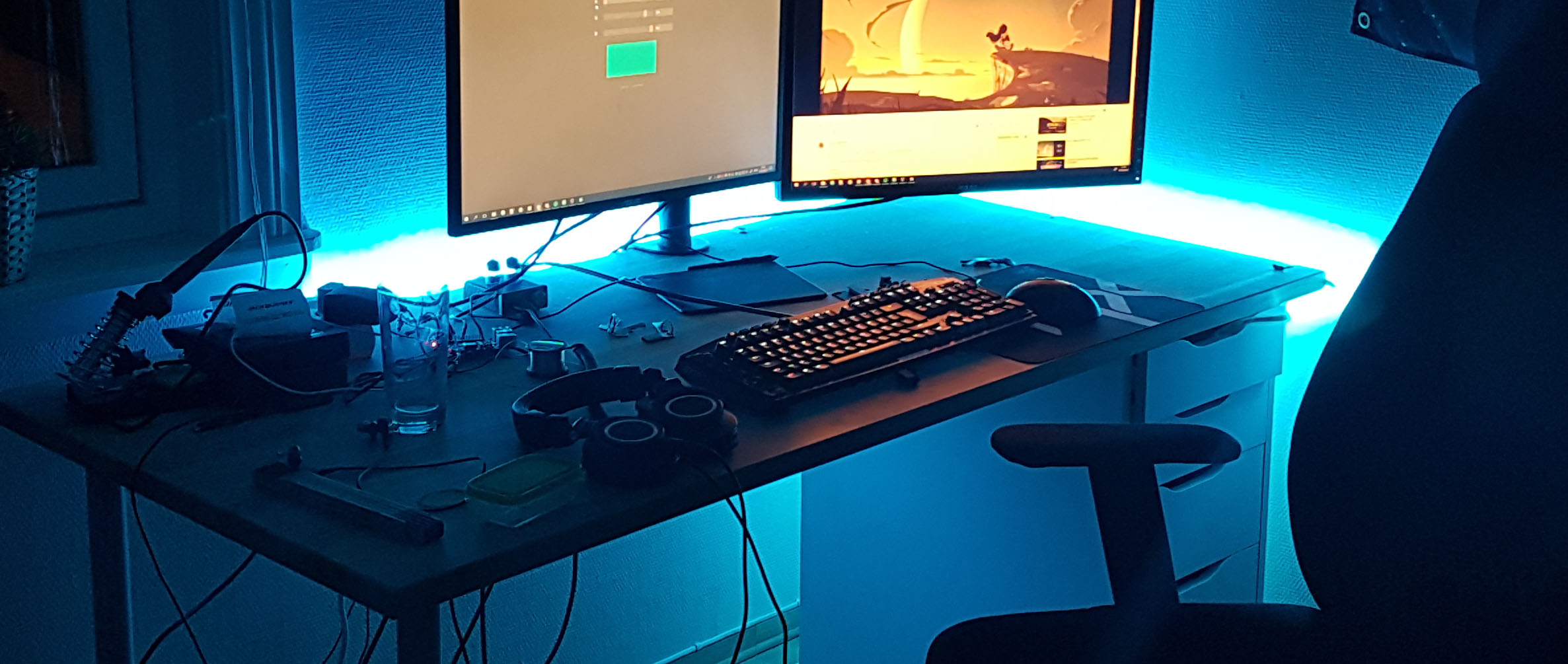
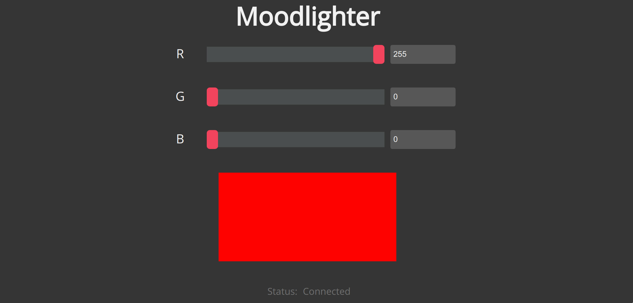
The goal of this project was to line the back of my desk with a strip of LEDs, which I could then control from my browser (on either my computer or phone). I also want a REST API to interface with. But the primary goal is to be able to run and create custom scripts easily.
My plan
I split this goal into two parts: hardware and software. The software is going to arguably be the most time consuming part, so I will split that into a second part which will hopefully come later in another post.
For the time being though, I will just use a modified version of an old control panel I made called Moodlighter.
Part list
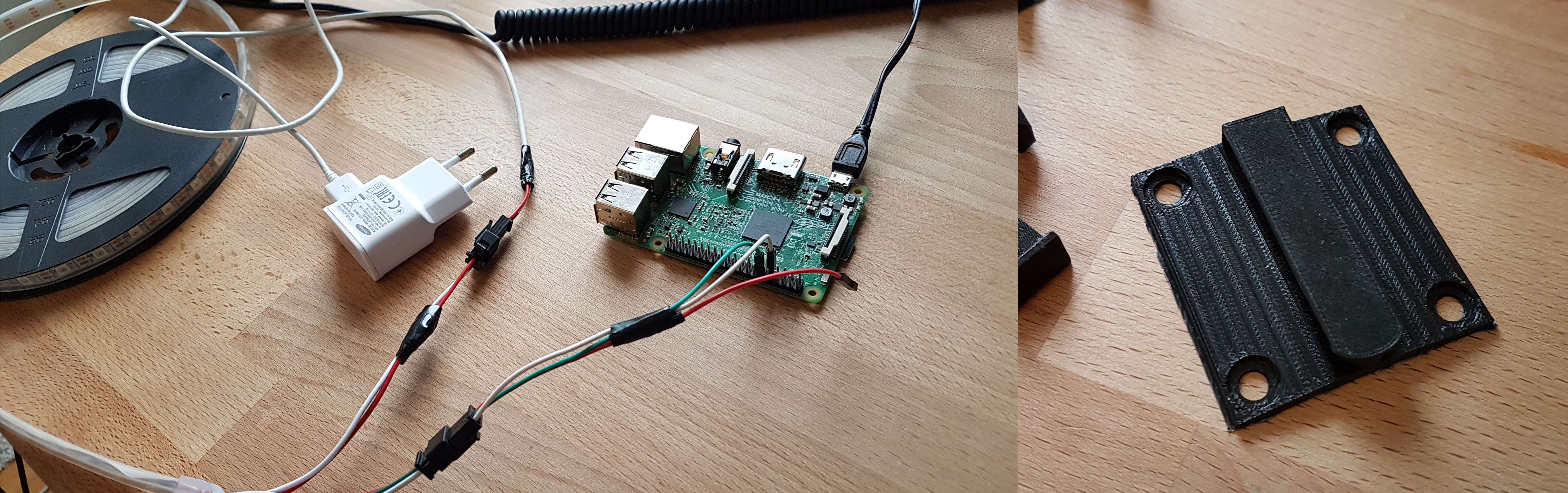
- Raspberry Pi 3
- 5m WS2801B LED-strip (from ebay a long time ago)
- Some cables, glue and solder
- Access to a 3D printer (to create the rest of the parts)
3D Printing
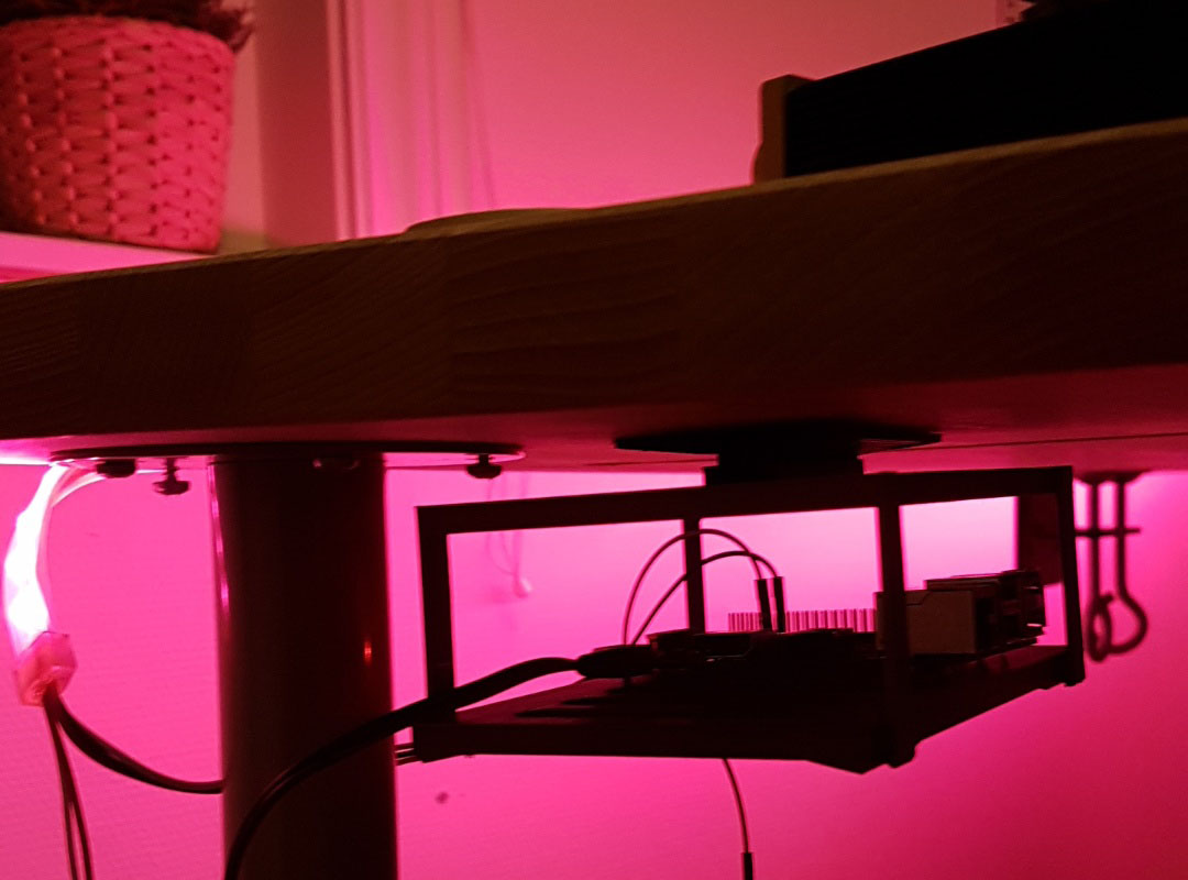
I decided I needed to print some pieces to help me mount the LED-strip on the desk, but I also wanted to mount the RPi under the desk.
- Some clips to put the LED-strip in
- Quick-n-dirty RPi mount
I used Tinkercad to create the designs. I used it because it easy and simple to use. I also didn’t want to spend all my time learning Fusion360.
Prototyping
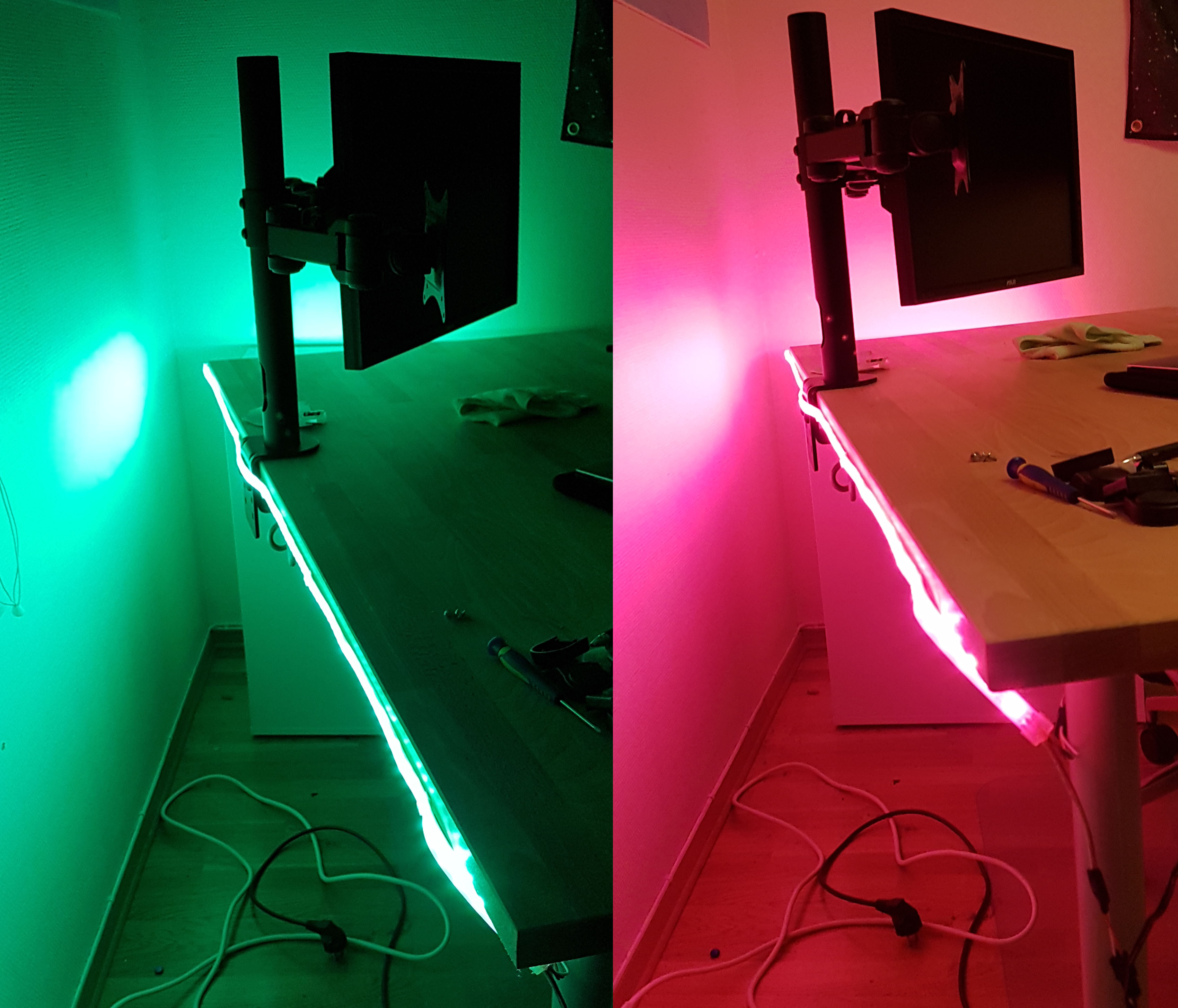
Here are some pictures of the first prototype clips. They ended up being way to big to fit the strip. My original idea was also to glue the clips under my table, because I was afraid I would see to much of the top of the clamps. I later changed my mind, and I instead ended up gluing them to the side of the table.
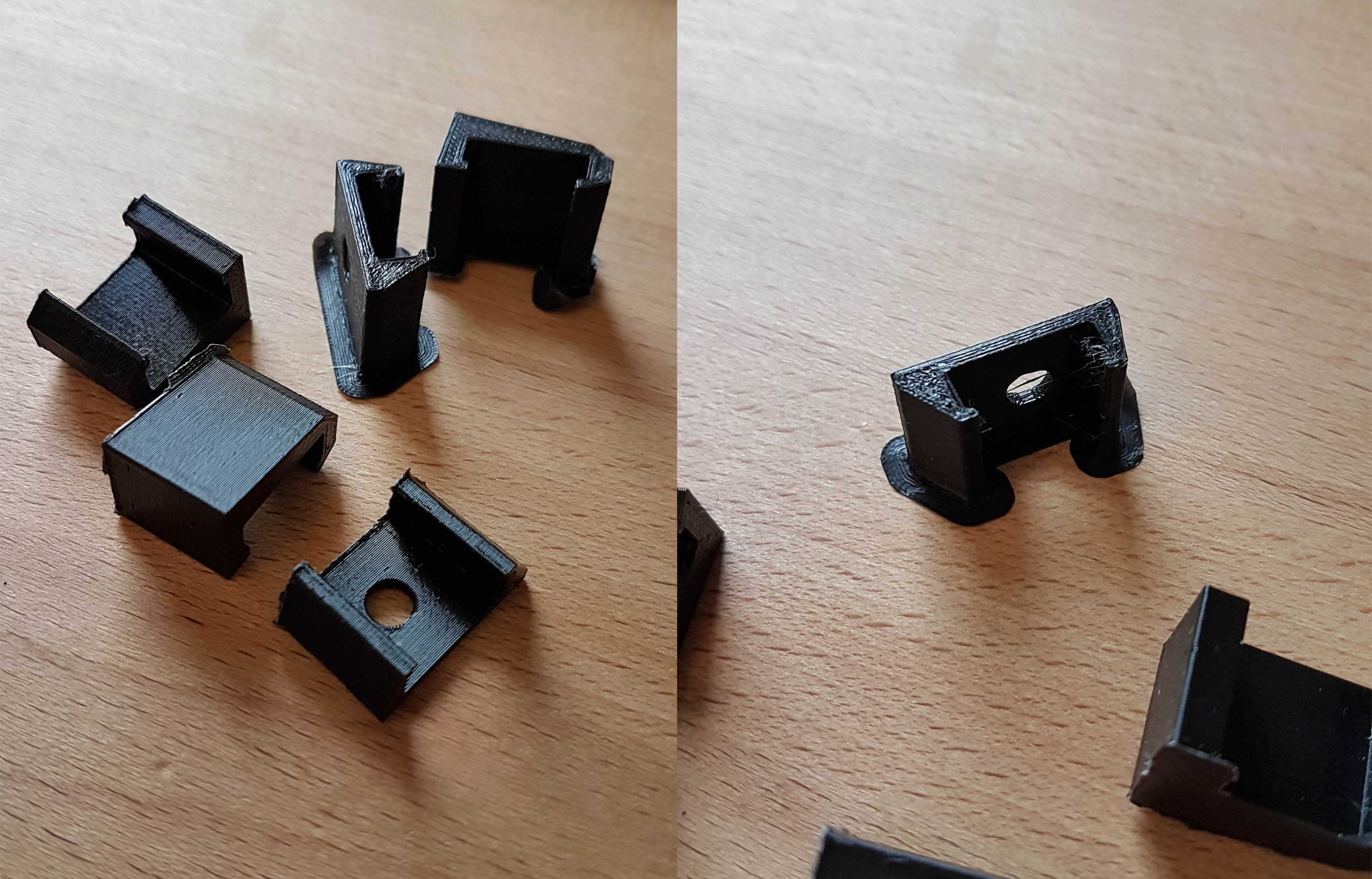
I ended up using one of those super accurate digital measuring devices to get the width and height of the strip. The strip I got from E-bay had a waterproof rubber-plastic cover, which made it quite easy to measure exact width and height.
I also changed the color to white. I had the original thought that the black clamps would blend more with with the table and strip, but after seeing it in person it didn’t give me the result I was looking for.
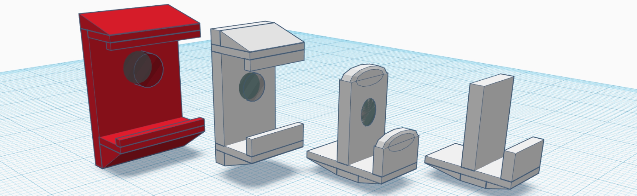
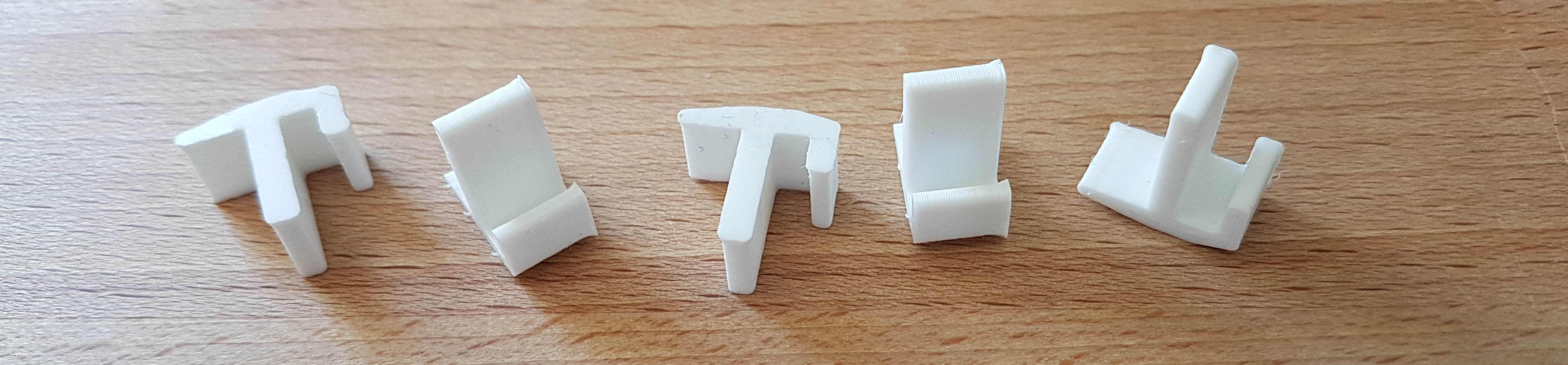
The new clamps fitted perfectly. I printed two variants, one with a “roof” and one without.
The second step was now to mount the RPi under my table. Now, first I thought I needed a lot of space to zip-tie cables, so that is why the plate is to large. I looks hideous, but it hangs out of sight so I’m okay with it.
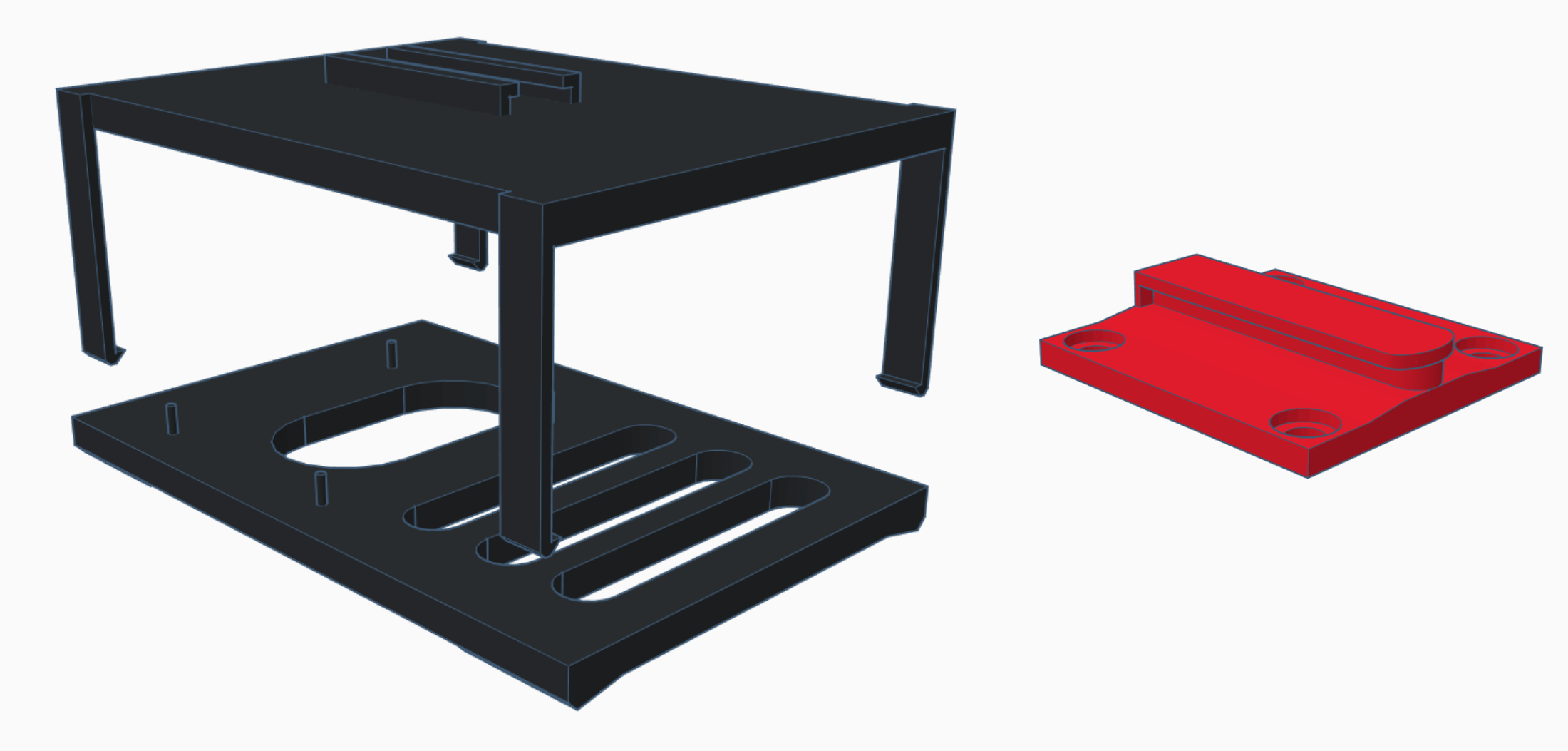
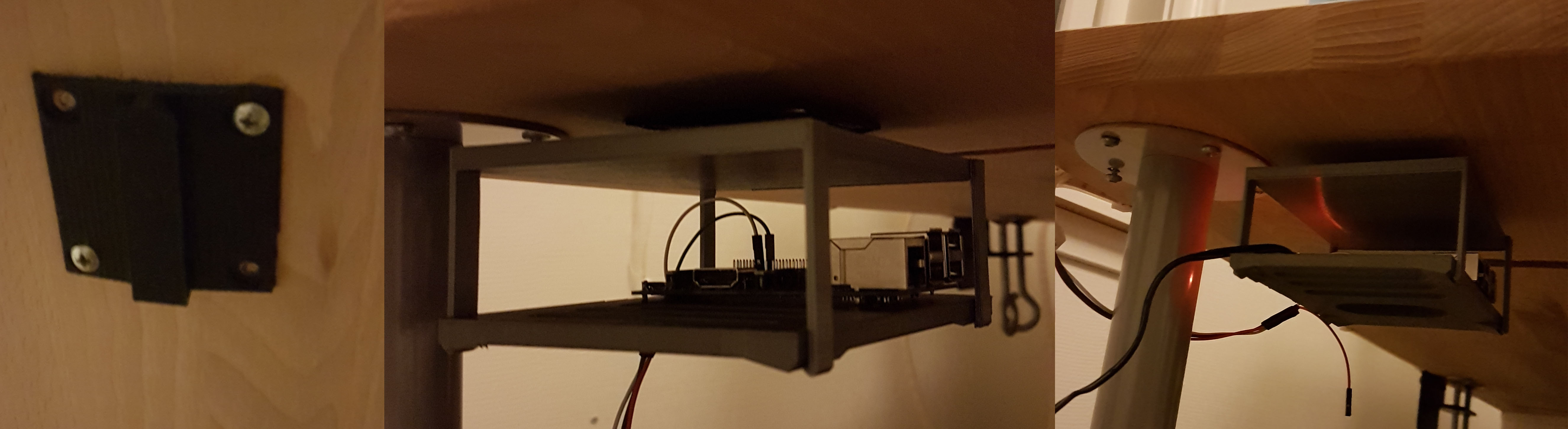
I made a little railing for the mount, so I could easily remove the Pi when I needed to.
I looked into modifying existing cases for Raspberry Pi’s on Thingiverse, and instead just mount it with some velcro, but at this point I had printed everything I needed and I had a lot of fun doing it.
The mounting rail has four screw holes. I didn’t think about the fact that it only needs to hold the Raspberry Pi, and not a full-size brick. In a re-design I think I could get away with only one screw to hold it in place.
Results
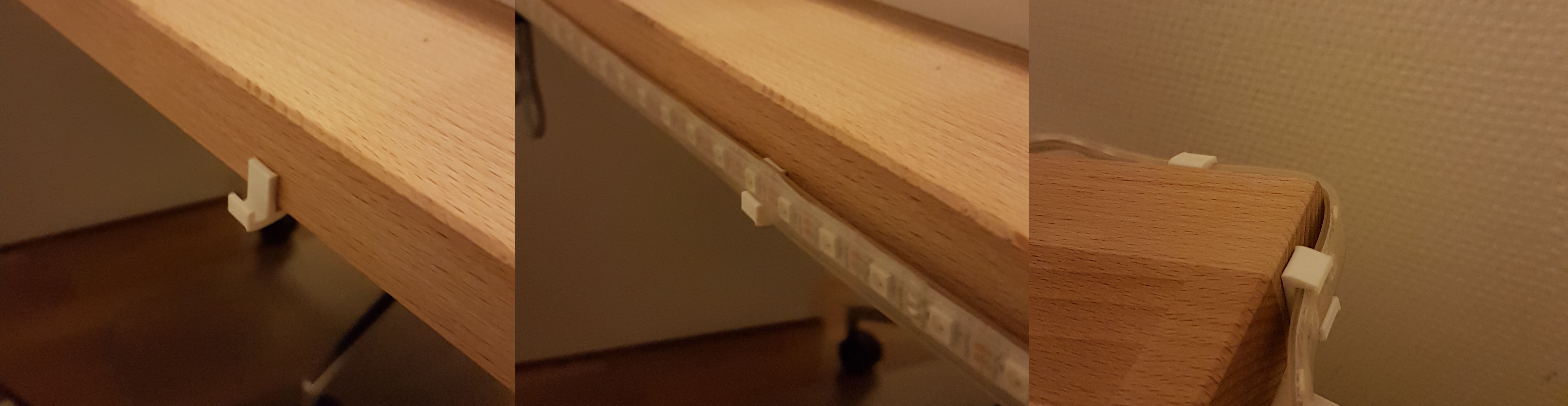
After mounting the Raspberry Pi and the strip clamps to my table I soldered on some new power- and data-cables. At this point everything is basically in place. It took be about four days to do complete, and I had a lot of fun doing it.
Here are some more result images: